TVRO:
Remove CPU/DSP unit by unscrewing three silver screws holding it down (the silver box on the top of the radio with copper taped sides) and pull up.
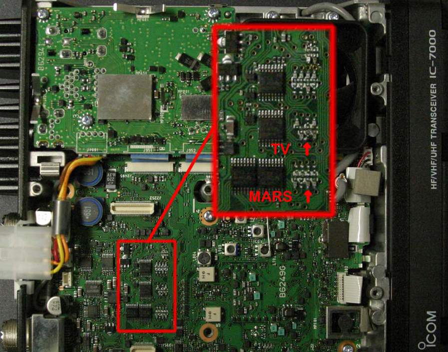
Locate four shift registers and bank of diodes - shift registers are 4094's. There are two next to each other and then a couple more. We'll call the two stacked the "left" ones
The "middle" shift register if looking from the front of the radio is the target.
Locate bank of SMT diodes (silver with "K" on top on one side) in front of the target shift register. They are in two columns, "left" and "right"
Unsolder one side of the second diode from the front on the left and lift up one side (or remove, slip to the side, whatever turns you on)
MARS:
OK - here's an out-of-band mod that does TX from 0-54, 118-173, 400-470.
Remove CPU/DSP unit by unscrewing three silver screws holding it down (the silver box on the top of the radio with copper taped sides) and pull up.
Locate four shift registers and bank of diodes - shift registers are 4094's. There are two next to each other and then a couple more. We'll call the two stacked the "left" ones.
The "left" shift register if looking from the front of the radio is the target.
Locate bank of SMT diodes (silver with "K" on top on one side) in front of the target shift register. They are in two columns, "left" and "right".
Unsolder one side of the second diode from the front on the left and lift up one side (or remove, slip to the side, whatever turns you on).
NOTE: The Automatic Repeater Shift on 2 meters and 440 is not affected by this mod! The Band Edge Beep, on the other hand, does not function.

|

