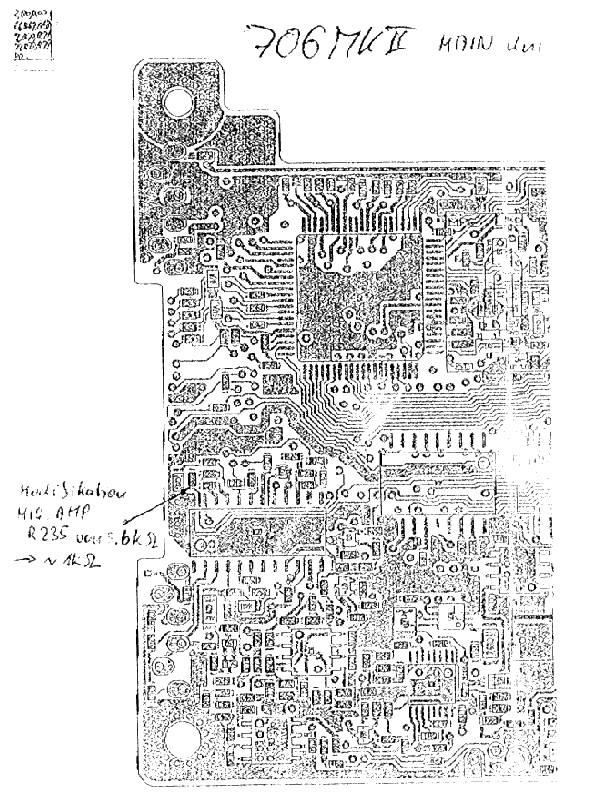
It is based on information provided by ICOM Europe.
The level of the IC 706 MK II microfone amplification does not satisfy under certain circumstances like heavy pile up or operators with faint voice.
A litle modification does help to increase the amplification level a lot: The 5,6 k ohm SMD type resistor R235 located on the main unit has to be replaced by an approximately 1,0 k ohm type.
After modification the personal level of the microfone amplifier can be set in the initial setup (menue Q2).
- To replace the resistor first open the top of the case by unsrewing the 3 screws in the middle and the 2 screws back on the left and right side. Remove the top carefully and disconnect the loudspeaker cable.
- Locate the main unit ( the one near the display front side) and disconnect all connectors.
- Locate the 5 screws holding the main unit and unscrew them.
- Pull out the main unit and turn it over. This is the side of interest.
- Locate the SMD resistor R325 and unsolder it. Solder in the approximately 1.0 k ohm type.
- Reassemble the main unit.
- A reset of the radio is not necessary.
- Don`t forget to set your personal mic amp level in the initial setup (menue Q2).
Remarks:
Although I modified my own IC 706 MK II without any problems I certainly will not be responsible for any damage of your radio following this modification description. You are acting on your own risk.

|
