Icom IC-746 (IC 746 IC746) transceiver mods reviews software and diagrams


ham | links
 Welcome to Motorola  submit to reddit
05 May 2024, 20:08 UTC 


Transceivers


Motorola

Icom IC-746 (IC 746 IC746)
IC-746
Programming interface schematics for Icom:
Programming software for Icom IC-746 (IC 746 IC746) :
PDF User Manual for Icom IC-746 (IC 746 IC746) :
PDF Adjusments Procedures Manual with schematics for Icom IC-746 (IC 746 IC746) :
Schematics for Icom IC-746 (IC 746 IC746) :

Mods for Icom IC-746 (IC 746 IC746) :
    Icom IC-746 (IC 746 IC746) improved AGC and weak signal volume
    Icom IC-746 (IC 746 IC746) adjustment point
    Icom IC-746 (IC 746 IC746) TX/RX frequency mod IC746 JA ver.
    Icom IC-746 (IC 746 IC746) Electronic Keyer Speed Modification
    Icom IC-746 (IC 746 IC746) Loss of tx power all bands
    Icom IC-746 (IC 746 IC746) Using 500Hz filters on SSB for Dig Modes
    Icom IC-746 (IC 746 IC746) Backlight
    Icom IC-746 (IC 746 IC746) modulation on AM
    Icom IC-746 (IC 746 IC746) (USA models) All Band TX Modification
    Icom IC-746 (IC 746 IC746) Schematic for ICOM CI-V Option
    Icom IC-746 (IC 746 IC746) Monitor Audio Output Too Low
    Icom IC-746 (IC 746 IC746) Solutions for chip blowing with mPC
    Icom IC-746 (IC 746 IC746) Power mod
    Icom IC-746 (IC 746 IC746) Separating the Tx and Rx lines
    Icom IC-746 (IC 746 IC746) Extended RX/TX
    Icom IC-746 (IC 746 IC746) Modification
    Icom IC-746 (IC 746 IC746) out of range TX/RX

Icom IC-746 (IC 746 IC746) technical specifications :  Icom IC-746 (IC 746 IC746) technical specifications


Icom IC-746 (IC 746 IC746) Electronic Keyer Speed Modification

Purpose

The built-in IC-746 electronic keyer speed is adjustable over the range of 6 to 60 wpm. Most amateur radio operators never operate Morse code approaching 60 wpm. I usually operate in the 15 to 25 wpm range and found that setting the keyer speed in this range is very touchy because the speed changes greatly with only a slight rotation of the Key Speed knob. This modification limits the maximum keyer speed to about 32 wpm making the adjustment of the keyer speed easier.

Modification

Solder a 1.5k ohm resistor across C8 of the S-LOGIC Unit PCB. If a maximum keyer speed other than 32 wpm is desired, increase the resistor value for a higher maximum speed, or lower it for a lower maximum speed.

Procedure

  1. Remove the top cover: 12 black screws and 2 chrome handle screws

  2. Remove the bottom cover: 6 black screws

  3. Remove the front panel assembly: 4 flathead screws; disconnect ribbon cable W18 that connects the S-LOGIC Unit PCB on the front panel assembly to the MAIN Unit PCB on the chassis by pulling it out of its socket (J1334) on the MAIN Unit PCB

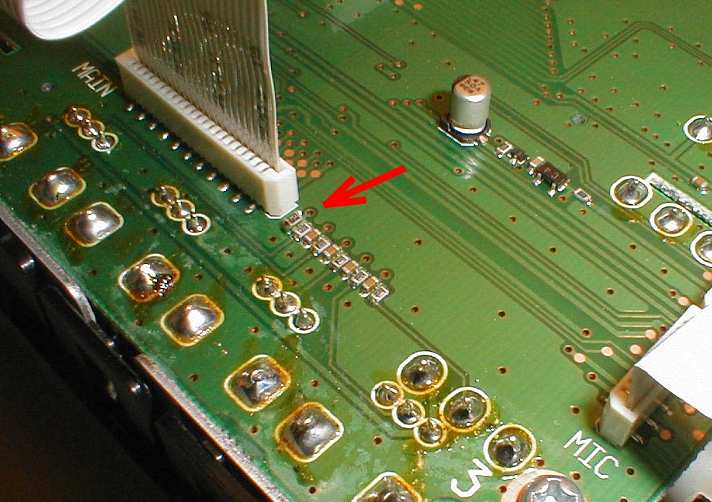
  4. Solder a 1.5k ohm resistor across C8 of the S-LOGIC Unit PCB. C8 is located next to pin 1 of J601. See photograph for location (red arrow). I used a size 0603 surface mount resistor. A leaded resistor may alternatively be used.

  5. Reassemble in reverse order of disassembly.