IC151) runs "hot" and think that failures are from thermal stress. In normal operation, IC151 dissipates 250 milliwatts (with 330 mW max rating at 25 deg C ambient). The legs of this very small MMIC chip become the heatsink for the 1/4 watt of heat generated. Adding an external heatsink for IC151 is cheap insurance against potential failure.
My heatsink requirements are as follows:
- no soldering to the circuit board,
- no drilling of the case,
- no epoxy on the chip,
- a thermal path to the aluminum case, and
- convective cooling fins.
Fabrication. The source of my aluminum heatsink is from Radio Shack (PN 276-1368). You have to make one cut with a hacksaw to reduce the length to 3/16 inch (5mm). Use a small file to remove the aluminum burrs.
Installation. The proper position for the heatsink is flat on the chip and touching the case as shown in the picture. The heatsink should be clear of any other components.
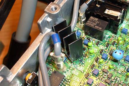
Unplug the gray cable with the black band and move it out of the way.
Apply a small amount of heatsink grease (as used in your PC)to the top of the IC.
Clean the heatsink with a solvent (like acetone) and apply a small amount of JB Weld epoxy to the top half of the heatsink wall. JB Weld has good thermal conductivity and good high temperature characteristics.
Place the heatsink into position as before and insure that it is flat on the chip.
Let the epoxy cure overnight. Check that the leftover epoxy has setup hard.
Position the loose cable in the heatsink slot as shown and reconnect it to the circuit board.
The heatsink may be removed at a future date to replace IC151 (hopefully not) by twisting it sideways with pliers.

