In the early 1980s Icom America marketed a group of transceivers and radios that utilized the latest state-of-the-art computer technology to enhance the operation of the radios. This technology improvement allowed hams to afford a reasonably priced high performance transceiver which until then was only available on units costing much more. Features now available to the hams included: higher frequency stability, better frequency resolution, digital frequency display, almost instant recall of saved frequencies (memory channels), quick mode signal processing and built in tones and offsets for the rapidly emerging repeater operation.
Implementation of all these features required a CPU with associated logic circuitry. In the early 80s, the most cost effective way to implement data processing and memory functions was through a DRAM (Dynamic Random Access Memory) to control the CPU. This DRAM was a volatile memory integrated circuit which required a lithium battery to retain its instruction set. The following receivers and transceivers had such RAM units:
IC-271 ; IC-471 ; IC-1271 ; IC-745 ; IC-751/A ; IC-R71A
The lithium batteries in these units typically lasted about 5 to 7 years before replacement was required. This was specifically noted in each of the Owners Manuals for the products.
This lithium battery can be replaced by the radio owner if care is used. The following is a recommended procedure to accomplish this:
Procedure
- Disconnect the power cable from the radio, and take the cover off.
- Unplug the RAM board and remove it from the radio.
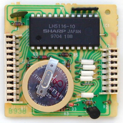
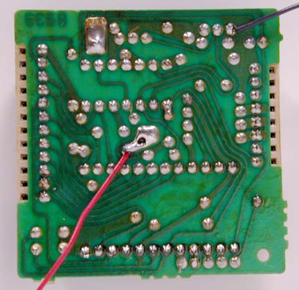
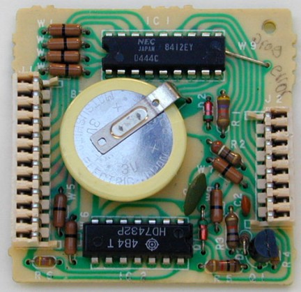
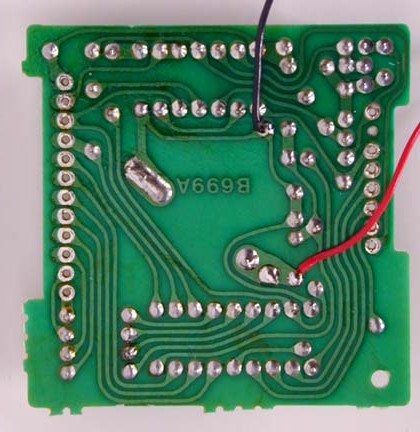
- Temporarily solder a 3 Volt DC battery source across the existing battery terminals (see suggested connection points on the circuit board pictures).
- Unsolder the old lithium battery and replace it with a new one. (BR2325 1HC, ICOM stock number 945 03112)
- Unsolder your temporary 3 Volt DC source.
- Reinstall the RAM board into the radio.
Cautions
- Do not use an AC powered 3 Volt DC source, your grounded soldering iron tip could short out the battery (+) terminal. Use a 3 Volt battery DC source only (2 alkaline cells for example).
- Do not solder the external DC wires directly to the lithium battery tab pads. If you do so, you will not be able unsolder the battery without having the wires drop off.
- If by accident you lose power to the RAM unit it must be sent to Icom America for reprogramming.
- Be careful not to damage or bend the connector pins on the radio side while removing or reinstalling the RAM card.
Pictures
There are two versions of the ICOM RAM boards. Both are identical in operation, and they are interchangeable. The differences are in the circuit board layouts only. Note that the black and red wires visible on these images are the suggested way of connecting the external DC backup voltage while the battery is being replaced. The wires are not a part of the RAM card, and should be removed when the battery replacement procedure is complete. Refer to the replacement procedure outlined above.
RAM card version A images:
RAM card version B images:
This modification can also be found at ICOM's own homepage on the following URL:
"RAM Card Backup Battery Replacement Instructions"
|

