Some IC-756PRO (-2) tend to oscillate on 6m. This is caused by a loop-back from the antenna relais (TX/RX decoupling) via the RF board, passing the persistently switched input attenuator (2 relais) and the RX/TX isolator diode D131. Hereafter the RX path joins the TX small signal route via IC151 to the final amp.
On 6m the decoupling of both the antenna relais and the decoupling diode D131 is no more sufficient. Depending on part tolerances the IC-756 oscillates on 6m or does not. When one of the attenuators is on (for sure not the default for 6m!) the decoupling might be ok. Even the antenna tuner changes the phase relation and can cause several go/no-go situations.
Two alternatives curing this ICOM implied design flaw are i) replacing the antenna relais and ii) replacing the decoupling diode by a better one. A third method iii) is to increase the input damping of the final amp (theres already a 3R-pi input attenuator). Their cure effect, and worse their side effects too, are hard to estimate. But theres also a fourth method iv) that is both most effective and simple:
As known from VHF/UHF antenna relais technique one can achieve huge decoupling values when earthing unused pins, i.e. adding a short circuit for the ports in off-conditions. For here a tiny reed-relais can add up several tens of dB decoupling.
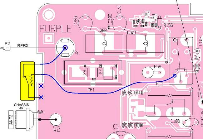
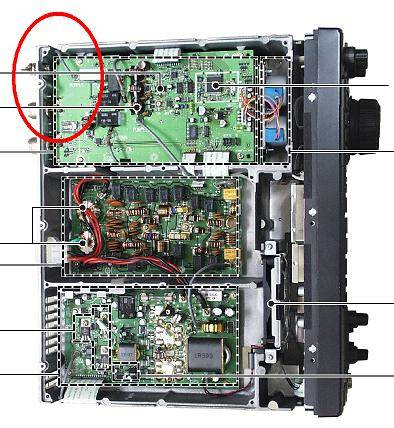
The best place for this patch-relais is directly on the CONTROL UNIT. Youll find it rear top of the 756. Remove the top lid, detach the speaker cable and remove a second internal shielding lid. For removing the CONTROL UNIT one has to de-solder both SO-239 connectors from the PCB. Also, be very cautious with the three printed flex cables.
The relais (use one w/o free wheeling diode) must be mounted on the top side because theres not enough room underneath (metal sheet cover of the tuner). Both ground connections can be re-used from the SO-239 solder point. For TX/+12V and RX/RF use some short and isolated wires. The longer one (TX/+12V) should be fixed, e.g. with self-gluing capton tape near MP1.
|

