Stop occurs from time to time, and may last for hours, minutes or down to part of a second.
Rig can work for many months without trouble.
Fault lies in counter unit. A foil path is not made according to wiring diagram.
Q25 is an amplifier for 1 mc cignal. Due to feedback through +5V supply, Q25 oscillates. This can be confirmed by looking with a scope on Q11 pin 15. The picture is unstable and shivering.
When measuring with a digital voltmeter on the same point, the voltage runs up and down,often very rapid. Upper limit is abt. +2,3V. When this voltage is low enough, rig stops to work,and start again when voltage increases.
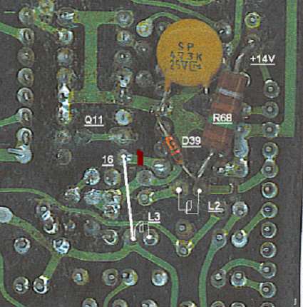
Q25 and Q11 get +5V feeded through L2 instead of through L3, due to a incorrect constructed foil path for +5V.
Loosen AF-GEN unit together with its attatched large aluminum angle. 4 screws in the right side of the PCB, 2 at the filter unit and 2 at the front. Do not unplug.
Bend PCB 180 degrees clockwise to get free access to the underlying counter unit.
Do the mentioned tests to ensure that this fault is present.
Unplug J9 to J14 on the counter unit.
Take out the counter board together with the display.
Interrupt the path going out from Q11 pin 16 on foil side,marked with red on picture.
Solder a jumper wire to Q11 pin 16 and left side of L3, marked with white on picture.
Reassemble.
Further info about counter unit:
On the components side of the counter unit,the printed markings of R12 and R67 are interchanged.
A resistor of 0,3 ohm is in series with the emitter of Q25, but it is not shown on wiring diagram.

|
