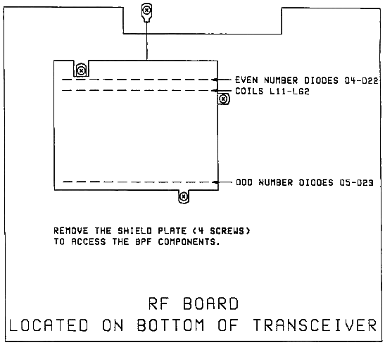
The TS-440S Control unit supplies band information to four circuits in the transceiver. The circuits are the receiver front end Band Pass Filter (BPF), the antenna tuner (AT), the transmitter Low Pass Filter (LPF), and the VCO circuits on the RF board that are part of PLL #1.
There are ten receiver front end BPFs that are diode switched into operation. If one of the diodes (D4-D23) becomes shorted or leaky, the band information is felt at two BPFs at one time. The voltage going through the bad diode will loop back to the VCO circuit, antenna tuner circuit, and LPF circuit.
The unwanted voltage will then create one or more of the following symptoms:
- PLL unlock (the transceiver only displays decimals).
- No antenna tuner operation.
- Low receiver sensitivity.
- Low or no transmit power output.
- Distorted transmit audio.
- RF feedback.
The most common symptom is the PLL unlock. To test the diodes, remove the large shield on the RF board to expose the BPF circuits. Reset the transceiver by holding in the A=B button as power is turned on. Even if the display only shows decimals, only the BPF for 14 MHz should be turned on. Using a DC voltmeter, measure the voltage at coils L11, L15, L21, L28, L34, L40, L46, L52, L58, and L62. Only coil L52 should measure 8 Vdc. The other coils should read 0 Vdc. If one reads 0.5 - 8 Vdc, replace the two diodes in that BPF circuit.
Coil/Diode/frequency range relationship:

L11  D4   D5           0 - 0.5 MHz        L15  D6   D7         0.5 - 1.6 MHz
L21  D8   D9         1.6 - 2.5 MHz        L28  D10  D11        2.5 - 4 MHz
L34  D12  D13          4 - 6 MHz          L40  D14  D15          6 - 7.5 MHz
L46  D16  D17        7.5 - 10.5 MHz       L52  D18  D19       10.5 - 14.5 MHz
L58  D20  D21       14.5 - 22 MHz         L62  D22  D23         22 - 30 MHz
Replacement diode part number
1S2588 or 1SS91S:    D4, 6, 8, 10, 12, 14, 16, 18, 20, 22
BA282                D5, 7, 9, 11, 13, 15, 17, 19, 21, 23

Time required to perform this modification is 1 hour or less.
|
