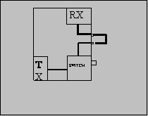
Problem:
This is a general transceiver problem. If you want to use the transceiver as part of a bigger setup (i.e. with external PA & preamp or with a transverter), it is convenient to have separate access to the RX and the TX of the transceiver. Otherwise you need two coaxial switches every time you add a new accessory. With split RX/TX paths you only need one switch - at the antenna. Furthermore split RX/TX paths eliminates the need for a change-over sequencer.
On the other hand it is also nice to have the transceiver working normally when you are using it barefoot.
Solution:
The solution is to jump wire the RX path (between RX and the RX/TX switching) trough the rear side of the transceiver with 2 BNC connectors. In normal state these connectors are connected via a short cable. In case you need to "split up" the transceiver, you remove the short coax cable, and you obtain direct access to the RX. The TX is still available using the common connector.
note: If you are always using your transceiver barefoot, without connecting any PA, preamp or transverter, this modification will offer no benefit.

Remove the back cover. If you place the holes for the BNC connectors next to and aligned with the two existing DIN-connectors, then ICOM have left enough space on the inside for the connections. You can also add other desired outputs like a phono plug for AF OUT.
The RX cable runs between J4 on the RF YGR PCB and the PA unit.
note: In my IC-275H the PIN-diode for the FM RF gain is shared with the RX/TX switch and placed in the PA unit. This means that the control voltage passes through the RX cable.
Therefore the breaking of the RX cable will cancel the FM RF gain function (the SSB/CW RF gain is working on the AGC and is not affected). The solution is to install a new PIN-diode (D5) on the RF-YGR PCB. The PCB has already room for it. To avoid short-circuiting the control voltage the jumper placed in stead of C86 on the RF-YGR PCB, should be replaced by a 1nF capacitor.
|
