The KENWOOD TS-2000 transceiver has a final intermediate frequency of 12 kHz. This frequency is suitable for a number of external applications, such as Digital Signal Processing (DSP) and an external DRM demodulator. Both digital signal processing and demodulation of DRM signals can be done with a PC with soundcard and suitable software. Unfortunately KENWOOD haven't made an 12 kHz IF Output. However, if you are comfortable working with surface mounted components and delicate electronics, you can make your own 12 kHz IF Output on your TS-2000. This modification is based on a description I received from LA6XJ Kjell Holen, and slightly modified by my self LA8OKA Martin Storli. My modifications is the use of the ACC2 Connector as a mean of permanent output, and the use of a 1 µF Capacitor. (Kjell Holen used a 22 nF Capacitor.)
Before you do this, please make sure you understands the consequences this modification or failure of this modification can lead to:
- The warranty of your TS-2000 will be void!
- You may damage your TS-2000 beyond repair!
- I will not accept any responsibilities or liabilities of what you or any other persons choose to do with your or anyone else's TS-2000 transceivers.
- If you have never done anything similar to this before: FORGET ABOUT IT!
- Working with electronics without paying close attention to safety may kill or seriously harm you or someone else!
- Make sure you know what you are doing!
Work description:
- Disconnect the power supply, all the antenna cables, the ground wire and any other cables and wires connected to the TS-2000 transceiver.
- Turn the TS-2000 transceiver upside down, with the front facing towards you.
- Remove the bottom cover.
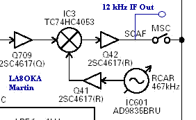
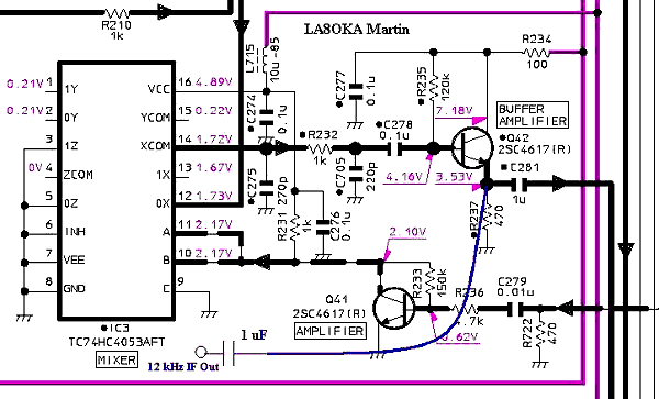
- Take a close examination of the Block Diagram in Fig. 1 and the Schematics Diagram in Fig. 2. Note that a new 1 µF Capacitor will be connected to the emitter of the Q42 Transistor. This is the new 12 kHz IF Output.

Fig. 1: Block Diagram showing the new 12 kHz IF Output in blue.

Fig. 2: Schematic Diagram showing the new 1 µF Capacitor and the new 12 kHz IF Output in blue.

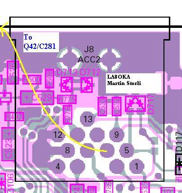
Fig. 3: The Printed Circuit Board showing the connection point of the 1 µF Capacitor.
Please note that Fig. 3 is component side view.
- Locate the surface mounted components, Transistor Q42, Resistor R237 and Capacitor C281.
- Isolate the leads of the 1 µF Capacitor. Solder one of the leads of the 1 µF Capacitor on to Capacitor C281 as shown in Fig. 3. Be aware, too much heat will damage Capacitor C281 and the Printed Circuit Board! Make sure that the leads of the 1 µF Capacitor does not connects to any other components.
- Solder the center conductor of a RG174 coax cable on to the free lead of the 1 µF Capacitor.

Fig. 4: The Printed Circuit Board showing the connection point at Pin 6 on the ACC2 Connector.
Please note that Fig. 4 is foil side view.
- Stretch the coax cable to the ACC2 Connector.
- Locate Pin 6 on the back of the ACC2 Connector, use a multimeter to do this. Pin 6 can be reached from the back of the ACC2 Connector. There is no need to remove the TX-RX1 PCB and turn it around, although this will make a better looking modification.
- Solder the center conductor of the coax cable on to Pin 6 on the back of the ACC2 Connector.
- Locate Pin 4 on the back of the ACC2 Connector, use a multimeter to do this. Pin 4 can be reached from the back of the ACC2 Connector.
- Solder the braid of the coax cable on to Pin 4 on the back of the ACC2 Connector.

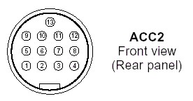
Fig. 5: The ACC2 Connector.
- You will now have a 12 kHz IF Output at Pin 6 on the ACC2 Connector on the back of your TS-2000 transceiver.
- Put your TS-2000 transceiver back together, connect the power supply and the antenna and enjoy.
To test your new modification, you can try one of these Software Demodulators:
Good luck!
|
