This modification is provided "as is", and is subject to change without notice. Kenwood Service Corporation makes no warranty of any kind regards to this modification procedure, including, but not limited to, the implied warranties of merchantability and fitness for a particular purpose. Kenwood Service Corporation shall not be liable for any error or for incidental or consequential damage in roujunction with the furnishing, performance, or use of the modification procedure.
It is illegal to operate outside the limits of your class license or permits.
- Disconnect the power cord and antenna coax from the transceiver.
- Remove the top and bottom covers.
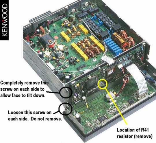
- Remove the top screw from each side of the front panel assembly.
- Loosen the bottom screw from each side of the front panel assembly.
- Carefully rotate the front panel forward to gain access to the Control board (X53-3690-10).
This board is mounted vertically against the body of the transceiver. It is not the board that is mounted in the front panel assembly.
- Locate and remove the chip resistor R41 from the Control board.
- Assemble the transceiver then perform the CPU reset procedure by holding the A=B button depressed as power is turned on.

This modification requires soldering equipment rated for CMOS type circuits. It also requires familiarity with surface mount soldering techniques. If you do not have the proper equipment or knowledge do not attempt this modification yourself. Seek qualified assistance.

|
