Some TS-950S/SD owners have reported a transmit spurious emission between 3.500 MHz and 3.520 MHz. The modification will reduce the spurious emission to - 65 dB.
Required parts:
10 pF capacitor           CC73FCH1H100J     QTY. 1
16 pF capacitor           CC73FCH1H160J     QTY. 1
12 µH coil                L40-1201-17       QTY. 1
2.6 X 4 mm screws         N09-0650-05       QTY. 4
- Disconnect the power cord and antenna.
- Remove the top and bottom covers (18 screws).
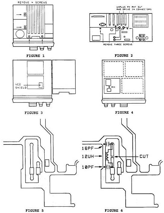
- Open the subchassis to expose the PLL board (figures 1-3). To open the subchassis remove 4 top screws, remove 3 back screws, and unplug the RX ANT OUT and DRIVE In connectors.
- Replace the four VCO shield plate screws with the type listed above. Figure 3.
- Close the subchassis and secure it with the screws removed in step 3.
- Locate the A.F. board on the bottom of the transceiver. Figure 4.
- Remove the board's mounting screws and disconnect the necessary connectors to expose the bottom of the board.
- Locate the foil pattern area shown in Figure 5. This area is below IC11.
- Cut the foil pattern and add the components shown in Figure 6.
- Assemble the transceiver. Remember to plug in the two connectors on the back panel.

This modification is covered under the 1 year warranty.
Time required to perform this modification is 1 hour or less.
|
