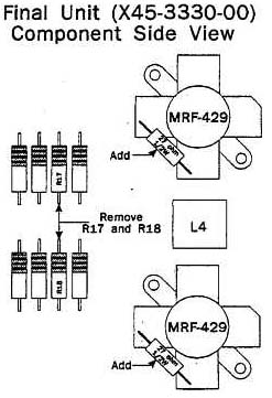
It is possible to exceed the maximum Vcbo rating of the MRF429 transistors used in the TS-950S/SD if the unit is operated at excessive transmit power levels (greater then the normal factory output power setting). This results in a collector to base short on the MRF429. This causes excessive current to be drawn thru R17 and or R18 of the final bias circuit. This can cause a large amount of smoke from the overloaded resistors. It does not normally cause damage to surrounding components. (You might wish to check Q7, VR2, Q8 and the fuse just as a precaution!)
R17 and R18 are carbon type resistors (27 ohms ½ w). Carbon resistors can emit quite a bit of smoke when overload in this manner and can be the cause of considerable concern by the operator!
In order to case operator concern we recommend replacing R17, and R18 on the final unit (X45-3330-00) with ceramic resistors whenever replacing the final transistors. These special resistors have been designed to open quickly if the current rating is exceeded. This prevents smoking and the odors associated with burning resistors.
Parts required:
27 ohm ½ watt ceramic resistor, (R92-1286-05)
Precautions:
- The MRF-429 transistors generally fail one of two ways:
- The collector/base junction opens. R17 and R18 are not damage when this occurs.
- If the MRF-429's are operated at RF power levels higher then the absolute maximum Vcbo rating the collector/base junction fails. This causes excessive current to flow thru the base circuit.
- If the MRF-429's short collector to base with ceramic resistors there will be very little smoke before the resistor opens. The outward appearance of the resistors will not change, so you must make sure to check the resistors with an ohmmeter before installing new finals.
- If R17 or R18 should open there will not be an appreciable change in the base circuit current. It is essential, however, that these resistors be in good working order as they ensure stable operation of the final amplifiers.
- R17 and R18 must be replaced whenever you replace the final transistors. The ceramic resistors are easy to identify. They are rectangular and white in color.
Replacement Procedure:
- Replace the bad MRF-429 transistors.
- Remove R17 and R18 from the component side of the Final circuit board.
- Solder the ceramic resistor directly to the base and emitter of the final transistors. The stability of the circuit is improved by soldering R17 and R18 directly to the base and emitter of the finals. Do not install them in the old locations!

|
