- Place the radio with the front panel toward you and bottom side / speaker
side UP.
- Remove the (4) screws located in each corner.
- CAREFUL! Go slow, you will need to disconnect the speaker cable while removing the cover.
Look at the lower right hand corner of the main printed circuit board.
- You should see a silver crystal with the number "D196D3C" printed on it.
- Just above the crystal, you should see an (8x8) matrix pad (see below diagram).
o o   o o   o o   o o
o o   o o   o o   o o
o o   o o   o o   o-o   <-- Remove
o o   o o   o o   o-o   <-- Remove
Note: there are ONLY (2) resistors in place. (Bottom right and the one directly above it).
- REMOVE BOTH RESISTORS [Do NOT attempt this unless you know how to use a low wattage soldering iron]
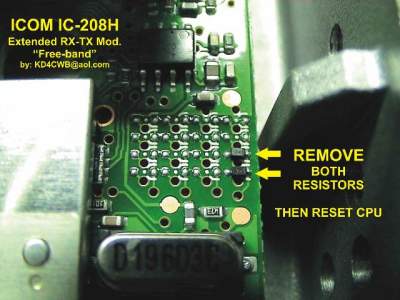
- RESET THE RADIO, hold the [SET LOCK] and [S.MW-MW] buttonsdown during
power-up.
DONE! New RX/TX Ranges
118.0000  -  135.9875    RX-AM only
136.0000  -  173.9875    RX & TX (15% RF power fall-off at lower freq, Full
                         power at high freq)
230.0000  -  399.9875    RX only
400.0000  -  478.9875    RX & TX (Do NOT transmit below 410MHz on HI-PWR,
                         VSWR fold-back)
479.0000  -  549.9875    RX only
810.0000  -  849.0000    RX only
849.0000  -  869.0000    RX only
894.0000  -  999.9875    RX only
|

