Problem:
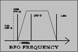
In these transceivers ICOM has chosen to shift the CW passband up 200 Hz compared to the SSB passband. This makes it more difficult to copy SSB signals in CW mode.
Solution:
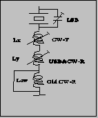
The extra BFO coil that is added in CW-R is short-circuited, and the BFO is re-adjusted for proper CW RX/TX-tracking and for preferred USB/CW passband.
Implementation:
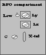
- short-circuit Lcw in the BFO compartment.
For readjusting the BFO you need another transceiver (TRX2) with correct tracking.
- Receive on TRX2 and transmit in CW. Adjust the VFO (with the RIT off !) of TRX2 until you have the desired side tone in CW mode. (e.g. 800 Hz - can be found by beating the tone with the side tone oscillator).
- Transmit on TRX2 and adjust Ly (CW-R) until you have the desired side tone in CW mode. (you are setting the ~800Hz difference between CW-R & CW-T).
- Adjust Lx (CW-T) for preferred USB/CW receive passband.
You might have to repeat the tuning once again, as there is some interaction between the adjustments (diode switching for high impedance RF circuits are not perfect !). If you would like to adjust the LSB passband, this should be done by adjusting the capacitor C, before adjusting the coils.


Note: The BFO coils are switched in successively to give the required offset from the LSB frequency. Therefore adjusting CW-T also changes USB/CW-R.
Re-adjusting all of the BFO frequencies is a good idea in any case to compensate for crystal aging. If the passbands sound different in LSB and USB it is a sure sign of mis-alignment due to crystal drift - they should be more or less the same.
Disabling of SBB squelch
Problem:
Squelching is nice to have in FM mode, but it doesn't really work for SSB, where you will be looking for weak signals. Therefore you have to adjust the squelch level every time you change mode. Furthermore I enjoy using FM as a monitoring mode on the SSB calling frequency, so changing the mode happens quite often.
Solution:
The solution is quite simple. Just cut the connection to the SSB input of the squelch circuit in some way.
Implementation:
The easiest way to break the connection is to connect the base of Q7 to ground. The base is the lead facing into the centre of the PCB.
|
