Okay, so you were serious about doing this mod to your radio. COOL.
To do this mod, you have to follow all the rules.
1.) You've spent about 200+ bucks for this radio, now go out and spend another 25 bucks on what you will need to do this mod successfully.
You will need the following equipment:
- A nice soldering iron and a BRAND NEW TIP!
- Some Radio Shack 60/40 thin low rosin core solder the good stuff
- Desoldering Braid (to suck up solder)
- Desoldering Pen (uses suction to suck up solder)
- A decent maginumfying glass (you will need this!)
- A damp sponge (to clean the soldering iron tip with)
- A clean and clear workspace with plenty of elbow room
- A small parts box of some kind to collect parts (hehehe)
- A steady hand, tall glass of water and a change of shorts when you get to the diode section. (this was funny, my wife came into the room and saw the radio in pieces and I was sweating with my mouth open and was drooling when I saw the diodes I needed to unsolder) Now remember, the radio was already disassembled and there was no turning back. OH CRAP!
- PATIENCE! This mod took me nearly 4 hours to complete.
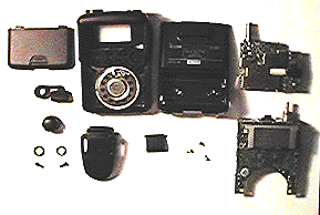
Just a preview of your workspace in a couple of hours!
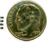
I GOTTA REMOVE WHAT!
These diodes are about as small as the tip of a lead pencil, you CAN do this if you want.
STEP 1
Orient the radio with it face down and the antenna pointing away from you. This is the orientation you will keep the radio at all times unless otherwise directed to do so. (I used a piece of felt to place the face of the radio on)
STEP 2
You should be looking at the back of the radio at this time. Unscrew the antenna and pull off the dial knob and place them in your parts box for now.
STEP 3
Unscrew the antenna and dial knob ferrules (this is the nut that holds the antenna connector to the case).
*** WARNING *** The SMA Antenna ferrule is held on with some kind of super glue in the threads so you will need to work this nut loose ever so carefully. Just a piece of information that you may find useful, all the ferrules on the radio rotate clockwise to tighten and counterclockwise to loosen. Thus the old saying (Righitie tightie, leftie loosie). I used a jewlers screwdriver and a pair of needle nose pliers and placed the tip of the screwdriver into one of the notches of the SMA ferrule and "TAPPED" ever so lightly until it began to move. This requires time so take as much of it as you need, no sense screwing up this mod before you begin. It will work loose so take your time. You might also want to remember that you will be taking out the RF module board later and the SMA connector must come out of the case so you will need to remove the nut SORRY. The SMA connector is also glued to the case but using the same "TAPPING" method above, you will work it loose (more on that subject later)
STEP 4
Once you have removed the ferrules in step 3, you can remove the battery cover and batteries from the radio to reveal two screws in the compartment. Remove these screws and place them in your box. Just a note, I taped the screws to a post-it paper and labeled them so I knew where the went when I was re-assembling the radio. Next lift off the rear cover by prying the cover from the front at the rear then up and towards you (keeping in mind the orientation of your radio as described).
STEP 5
You should now see the RF board (daughter board) on top of the main board inside your Q7A. WHEW!
STEP 6
On the RF BOARD! there is one visible screw located on the right side, see figure 1.4 below:
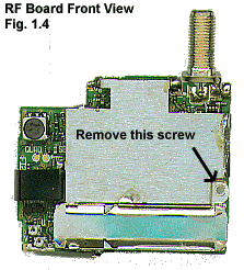
STEP 7
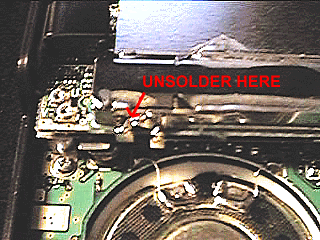
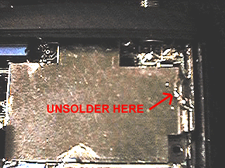
There are three points where the shielding for the RF board has been soldered to the lower board. One is in the lower left corner just above the ferrite inductor figure 1.5 and along the right side of the RF board next to the PTT button figure 1.6 and in the upper left corner near the blue assembly of the dial figure 1.7
| Figure 1.5 |
Figure 1.6 |
Figure 1.7 |
 |
 |
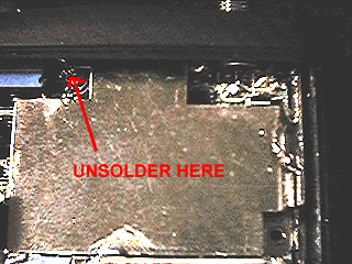 |
Unsolder Figures 1.5, 1.6, and 1.7 with the solder sucker and desoldering braid to wick up any left over solder. Be careful not to melt the plastic case in the procedure in figure 1.7.
*** WARNING *** ONLY, do a small spot at a time. DO NOT OVERHEAT sections. If you don't get all the solder in one time, don't worry, let things cool down a bit and go back for more later when it cools.
STEP 8
Once you have removed all the solder from the above steps, lift gently with your FINGERS ONLY, the rear of the RF board until the connector on the RF board figure 1.8 dislodges from its counter part on the main board, figure 1.9, use your fingers only because of the surface mount components which are located near the edge of the circuit board, you don't want to pry off any of them with the blade of a screw driver.
| Figure 1.8 |
Figure 1.9 |
 |
 |
Once you have dislodged this connector, the RF board will "Rock" clockwise just a little bit and tap gently on the SMA connector at the same time to dislodge it from the plastic housing (remember, it's glued so be patient). DON'T TAP TOO HARD, the RF board has inductor coils near the SMA connector end that if they get jammed into other parts of the radio could effect performance later. BE GENTILE!
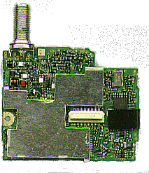
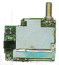
You should now have the RF board completely removed at this time: Figures 1.10 and 1.11 shows both sides of this board
| Figure 1.10 Bottom View |
Figure 1.11 Top View |
 |
 |
STEP 9
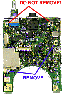
Remove the screw on the right hand side central to the PTT, and FUNC button. And the one on the left just bellow the little shield. DO NOT REMOVE the two top corner ones they hold the LCD assembly!!! See figure 1.12 for which screws to remove.
Figure 1.12
STEP 10
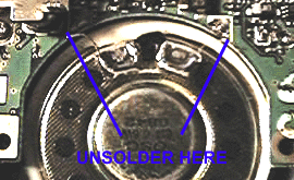
Desolder the two speaker wires from the speaker. Lift the bottom of the board out till the LCD clears its mounts in the case and pull the board out GENTLY so the rubber seal and the rubber keypad is not dislodged. If they do, just re insert them. See figure 1.13 for speaker solder joints.
Figure 1.13
STEP 11
Turning this board over with the LCD now facing you there is position for 7 SMD diodes marked A or A2 on the right hand side just above the central mounting point. All have to be removed I had 4 in my radio! See figure 1.14
Figure 1.14
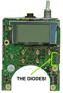
Figure 1.15

The easiest way that I have found of removing the diodes without damaging them or the PCB assembly is to heat one end / contact of the diode with a custom tip I made (pretty ingenious I think) figure 1.15 and using a desoldering braid to wick up the solder and lift that end with a small pointy screw driver (jewlers type works good) **** NOTE **** You don't have to pry the diode up, it just needs to clear the PCB a fraction. Remember, DO NOT over heat the diodes or the contact, this could cause the PCB trace to lift off of the board, that would be a bad thing.
Once you have removed the diodes, take a break! You deserve it.
STEP 12
The re-assembly. The re-assembly is pretty simple. Reverse the procedures. One point of note is when you come to re-applying solder to the RF board to the main housing. Be careful to not apply too much solder so it leaks down into the radio and also do not over heat ANYTHING!
|
