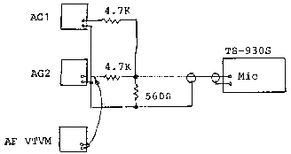
This procedure will allow a simplified alignment method for the TS-930S CW VRT section, when a VBT-1 jig is not available.
Test Equipment required
- Oscilloscope
- Audio signal generator (2)
- AF VTVM
Procedure
- Preset the TS-930S controls as follows:
- MODE: …………………. LSB
- Disconnect the DRV connector from the Signal unit.
- Confirm that CAR2 frequency is the same when switched from transmit to receive. If it does not stay constant adjust VR23.
- Connect the oscilloscope probe to R176 in the Signal unit.
- Connect the two Audio Generators as shown in the figure below. Set AG1 to 300 Hz and AG2 to 2.9 KHz.

- Ensure that the output level of AG1 and AG2 are equal by using the AT VTVM.
- Connect the cathode of D133 to that of D132 in the Signal unit using a 0.01 µF capacitor.
- Clip the lead of D124 and place the STBY switch to SEND.
- Adjust TC4 (CAR1 8.8315 KHz for USB) so that complete tone waveform is observed, as shown in figure 2. Return to REC, and resolder D124.

- Remove the 0.01µF capacitor installed in step 5.
- Set STBY to SEND and adjust TC3 (CAR2 8.375MHz) so that a complete two tone signal is displayed, as in Figure 2.
- Return to REC, and reconnect the DRV connector. This completes the simplified alignment procedure.
|
