Remove the antenna, belt clip, battery, and top volume & squelch/knobs
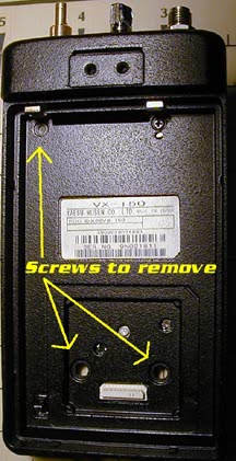
Remove the the black sticker (the one with the Ni-Cd battery disposal warning) and the small "sub-board". See Fig 1 *removing the sticker/sub-board reveals two smallphillips screws.

Fig 1 - Sub-Board
Remove the two screws that were under the sticker and sub-board, and remove the top LEFT screw - leaving the right screw alone. See Fig 2

Fig 2 Remove screws
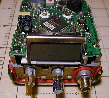
Remove the rubber grommets under the volume & knob controls, and using a pair of hemos or small needle-nose pliers, remove the nuts for the volume & squelch/knob.

*Photo shown with nuts and case removed
Carefully slide the front and back case apart and remove the rubber piece around the mic element.

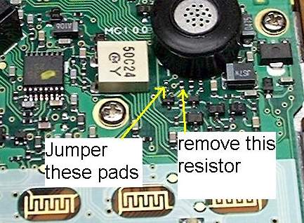
Fig 3
For Mars/Cap(140-174Mhz TX) remove R1275, and solder it to the blank solder pads labeled R1274 - Fig 3.
For Freeband (100-200Mhz TX) remove R1275 - Fig 3.
| R1274 | R1275 | Transmit Coverage |
| Blank | Soldered | 144-148Mhz (Factory Config) |
| Soldered | Blank | 140-174Mhz (mars/Cap) |
| Blank | Blank | 100-200Mhz* (Freeband) |
*The VX-110 & VX150 can be opened for 100-200Mhz, but the radio's circuitry is not wide-banded enough to cover the entire 100-200Mhz spread. When the radios display starts flashing/blinking, this means the radio's VCO is out-of-lock and no receive or transmitting is possible. A typical radio should RX/TX from approx. 125-180Mhz when the freeband mod is performed.
Reassemble the radio carefully. Most of the time resetting the radio is NOT necessary, but have a backup of your frequencies just in case, because the radio will reset itself most of the time after a modification is made.
I have noticed a major bug in the memory channels. This bug has to do with memory channel #1. Example: Lets say you program: ch. #1 with 147.000, and ch #2 with 154.570, and the last channel (I will call ch # 200) in your memory bank with 144.000
So......
| CH 200 | 144.000 |
| CH 1 | 147.000 |
| CH 3 | 154.570 |
Now, go to memory channel 1, and it will be 147.000, but rotate the knob to memory channel 2 (154.570) and back to 1, and the memory contents from CH 2 are now in CH1, which is 154.570 on memory channel 1(should be 147.000). The same thing will happen if you go to memory channel 200, and rotate knob one click to to memory CH 1, the contents from CH 200 will be on CH 1. This bug does not rewrite the memory contents in CH 1. This bug basically moves the frequency from the memory channel below CH 1, and above CH 1 to memory CH 1 while your rotating the knob through the memory channels. Scanning seems OK, and is not affected by the memory CH 1 bug.
Solution #1 for this is to make CH 200, CH 1, and CH 2 all to the same frequency. OR
Solution #2 set the "edge beep" to on. <---thanks goes to Susie for this info!!

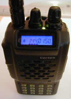
My VX-150 with the LCD display LED changed to Blue. The original LED was removed and replaced with a blue SMT LED (1206 size). R1239 (220Ohm) was removed and replaced with a 0 Ohm resistor.
| 