Controlling the memories and settings in the VX-7R is very hard, and you have not a general view. It is the same problem with the VX-5R, and this interface can also be used for VX-5R.
I found the schematic diagram for the original ADMS-1G serial interface on the internet, so why buy when I can make it.
I have seen this interface built with discrete component, but it needs lots of space, so I decide to make the interface with SMD component so the interface could be built in the serial connector. I have a extension cord, that convert the 9-pol. to 25-pol., and this give me more space to the interface. Note, that this PCB layout can't fit into the 9-pol. D-SUB connector, only 25-pol.
The schematic:

Parts list:
Q1   BC847b         (NPN)
Q2   BC847b         (NPN)
Q3   BC847b         (NPN)
Q4   BC847b         (NPN)
Q5   Not Used
Q6   BC856b         (PNP)
Q7   BC856b         (PNP)
D1   1N4148
D2   5,1V zener
D3   1N4148
D4   1N4148
R1   47K
R2   47K
R3   10K
R4   12K
R5   470K
R6   47K
R7   47K
R8   47K
R9   100K
R10  100K
The interface use other transistors than the original interface, but it is general purpose transistors and have no influence for the function. I used BC847b for the NPN and BC856b for the PNP.
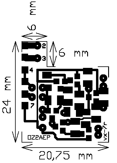
The print layout have you here. Click on the layout to download a PDF file with the print layout in 1:1 scale.
Here is the placement of the component. Remember that the component should be mount on the same side of the copper.
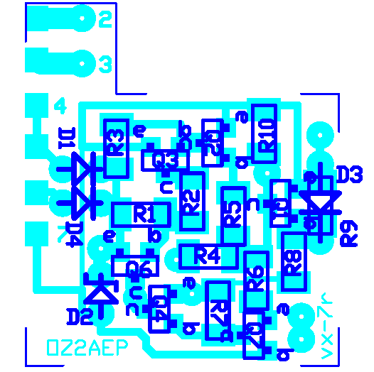
When you make the interface be very careful, the PCB tracks are very close, some places are there only 0,3 mm between the tracks.
Here you have the jumpers that should be solder on the opposite side of the component.

The PCB layout fit directly to the 25-pol. D-SUB connector, you should only solder few wires on the PCB, and connector. Make sure that your solder iron are small, don't used a solder tip that are over 2 mm.
If you not have experience and are familiar with soldering SMD, donít begin building this interface. The component are very close, and the pads are also very small, so be very careful when you solder the component, its easy to short two pads during the little space.
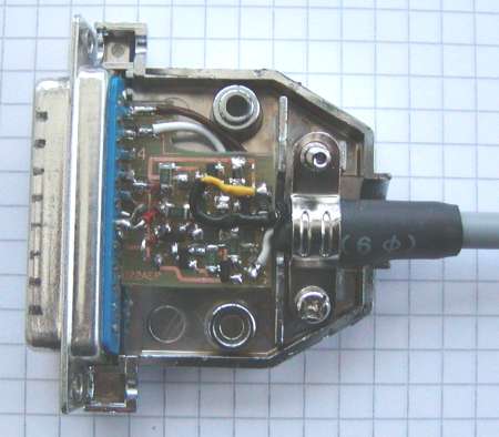
The complete interface solder to the 25-pol D-SUB connector.
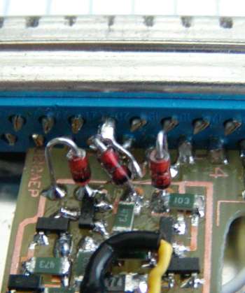
Remember to short pin 20 to 4. Here I use the diode D4.
The data connector on the VX-7R is a stupid connector. 3,5 mm mini jack with four connector and worst of all, it have threads. This connector is very difficult to find in local store, and when I have seen the description on http://home.comcast.net/~sllewd/vx7rhardware.htm to modify a standard 4 pin connector, I will try to do the same procedure.
If you are a VX-5R used see here.
It work fine, and here I give you my description with pictures.

First you have to take off the plastic cover, and then with a file, grind the metal off.
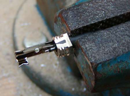
Here I have grind off the metal so the plastic is visible. Do the around the connector.

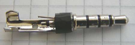
The connector should look like this. Note that there are some mark on the connector, this is from the vice. The diameter of the black plastic must not be over 5,0 mm, then you can't plug the connector into the VX-7R data jack.
Note, that I have solder all the three conductors and the shield. To the data I use the white wire, but I have solder the other wires for other experience.


This cable have I used with the VX7 Commander software, and it is working very well.
If you are a VX-5R user you have to grind off some of the metal. Else you can't plug the connector correctly into the VX-5R.
Take off the plastic cover and grind off the metal with a file, so the connector look like this.

Make sure when you plug the connector into the VX-5R, that the plug can go into the recess.
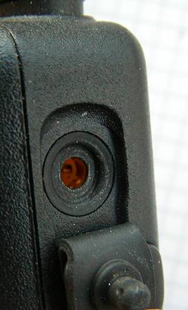 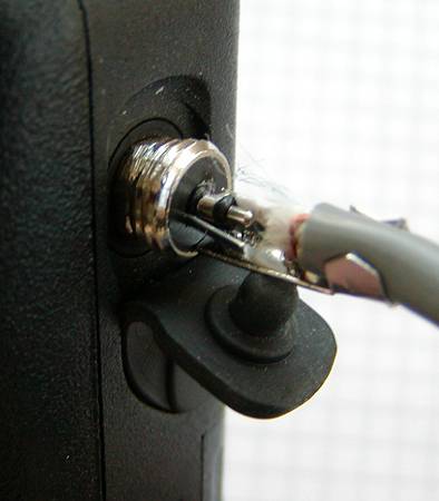
Cut 3 mm off the plastic cover and screw it back on the connector, then it look like this.

| 