Risk: You will loose the warranty.
Fun: You will have a fantastic rig with a 2.4 Khz Collinsfilter in SSB transmit and receive path and a 500Hz CW filter in the Narrow position for CW and DIG (Pactor, PSK31 etc.
The FT-817 comes with only one slot for additional filters but there is sufficient space to mount both SSB and CW if you remove the PCBs of the filters and wire them directly to the MAIN UNIT.
For the details see the Operation Manual on page 74.
The original filter CF4 will be removed and replace by the YF-122S SSB filter.
The YF-122C CW filter will be directly wired to the mounting pins og the optional filter socket.
There is no need to work on SMD components, but you should be very familiar with the tiny circiuts and have the right equipment, if not ask a expirienced OM to help you.
- See page 74 of the Operating Manual and follow steps 1 and 2.
- Remove the PCB MAIN UNIT, watch on the battery conector and the 3 pin connector in the middle of the board. Remeber or mark the position of the 2 coax-connectors.
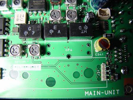
- Desolder and remove the original ceramic SSB filter, see picture
- Desolder and remove the filters from there original PCBs
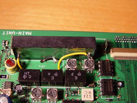
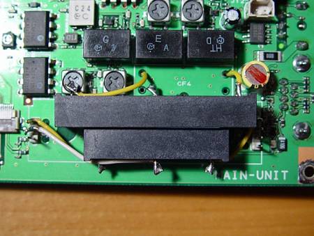
- Connect the SSB Filter with 3 short wires instead of the ceramic filter, see picture
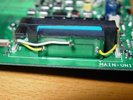
- Connect the CW filter with 3 short wires to the pins of the optional filter connector, see picture
- Fix the filters in there position with a small ammount of glue
- Reassemble the Main Unit, look carefully to the battery connector and the 3 pin connection in the center of the board
- Follw the steps 4 to 7 on page 74 of the Operating Manual
...and enjoy the clear signals from the Collins filters.
Vy 73 de Lutz, W4/DH7LK
Original SSB Ceramic Filter removed:
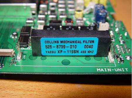
Position of SSB filter:
SSB filter wired:
CW filter wired:
Ready:
|
