WARNING:
In order to build the interface described below, you will at least require some basic electronics experience. If you don't understand, how the described circuitry works, it's best not to build it. Although the described procedure is relatively simple, you could cause serious problems to both your PC and your Motorola radio. So please build the interface and use it at your own risk.
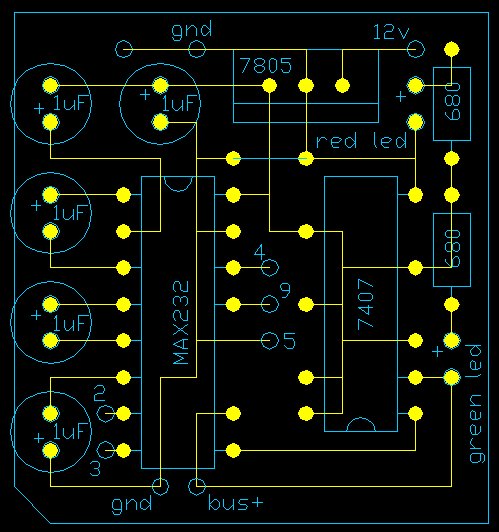
Pay attention to the polarity of the capacitors these are marked with a + in the diagram next to each capacitor. You will find that in some cases the capacitors appear to be the wrong way around, however this is not the case, as they must be configured this way to generate the correct voltages within the MAX232.
Interface Parts List.
Item        Qty        Description

 1           1         PCB (Single sided prototype board)
 2           1         IC MAX232
 3           1         IC 7407
 4           1         IC 7805 (5v regulator)
 5           5         Capacitors 1uf, 16v electrolytic
 6           2         Resistors 680 ohm 1/4 watt
 7           1         LED Green
 8           1         LED Red
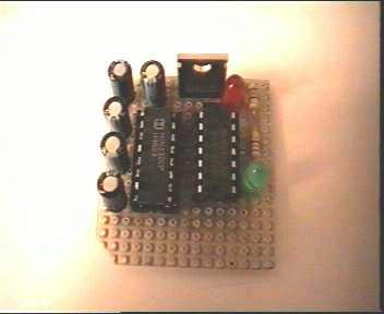
Component Side View

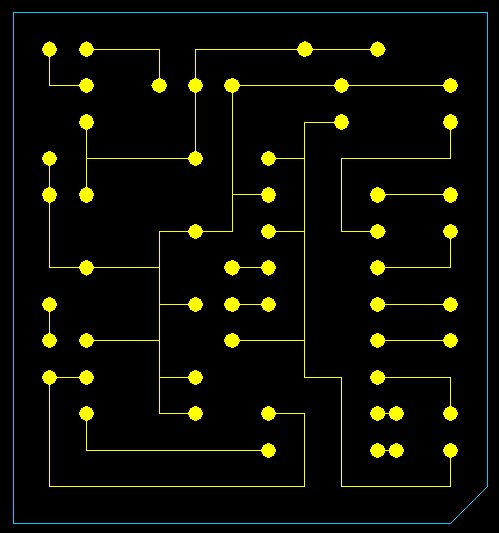
Track Side View

Download a zip file that contains an AutoCAD 14 file of the images above.
PC Connection.
In the interface drawing above you will see the numbers 2,3,4,5 & 9. These numbers represent the 9pin serial port found on most PC's today. If you only have a 25pin serial port then see below for the pin-out translation.
9 pin to 25 pin conversion information.

      9 pin                         25 pin

        2---------------------------3

        3---------------------------2

        4---------------------------20

        5---------------------------7

        9---------------------------22
Radio Connection (GP300).
To connect to your GP300, all you have to do is temporarily connect your interface to the GND and BUS+ on the back of the radio. these connections are visible when the battery is removed.
You will also need a external 7.5vdc supply to power the radio when you are programming it. This is connected between the 7.5 volt and GND connection on the radio.

Notes:
If you have problems getting this interface to work on your GP300, then try replacing the two 680 ohm resistors that feed the LED's. If you use 4.7k ohm it should work OK. I found that when using version R01.00.00 software I have no problems with the 680 ohm resistors, but for some reason when I ran the newer software (R08.02.00) I had problems reading the codeplug etc. All I have done is replaced the 680 ohm with 4.7k ohm and it works fine now with both versions of software. You will have to experiment a little and let me know what resistors work for you.
Simon VK4TSC encountered a problem where the GP300 being programmed/read will fail to pass data to/from the computer with an Error #2 (Serial Bus Error). After checking the BUS+ line with a CRO it was found that the GP300 could not properly switch the data bus, this being caused by the led/resistor combination on the data bus drawing a little more current than the radio could supply. By changing the series resistor to 1K ohm instead of 680 ohm the problem was overcome
The better solution maybe to use a spare gate from the 7407 to drive the led separately. Disconnect led cathode and link it to pin 4 of 7407, isolate pin 3 of 7407 from 5V and link it to pin 2 of same chip. The original 680 ohm series resistor can be left as is. BUS+ is now isolated from the data led.
The Interface design above has been tested on the following radio's:
GM300 (Connect to the Mic socket on the front panel of the GM300)
GM350 (Connect to the Mic socket on the front panel of the GM350)
GP300 (See this page for info etc.)
Maxtrac 840 - 800 MHz Truncking Radio (Try http://www.batlabs.com for connections).
| 